Trackspec's Exige S240 Project: Part 13, K24 Swap Rewire- Emtron ECU and AiM PDM32
Rewiring the K24 Exige
It’s been over 3 years since I put the Honda K24 into our Lotus Exige and it was the first car that I made an engine harness for. Although the harness was reliable and never gave me any issues, I felt that my harness building skills have improved much since then. What I really wanted to do was get rid of all of the unused wiring and the mess under the dash.
Hardware
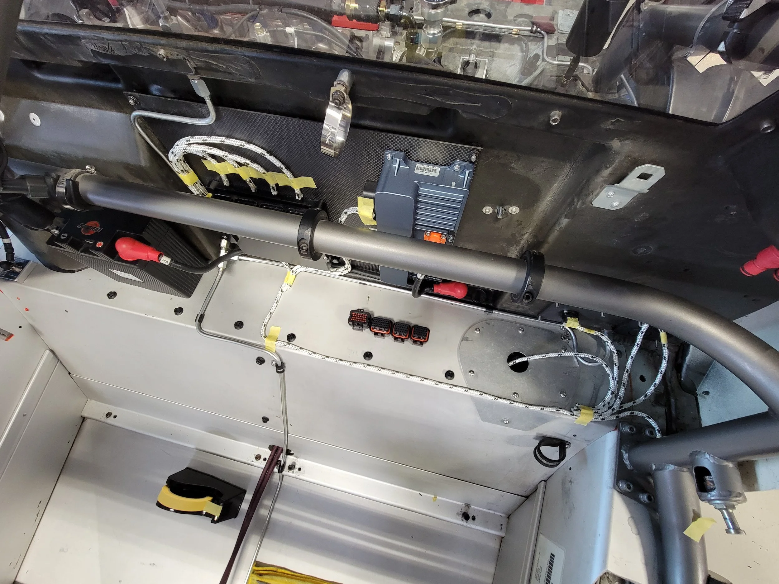
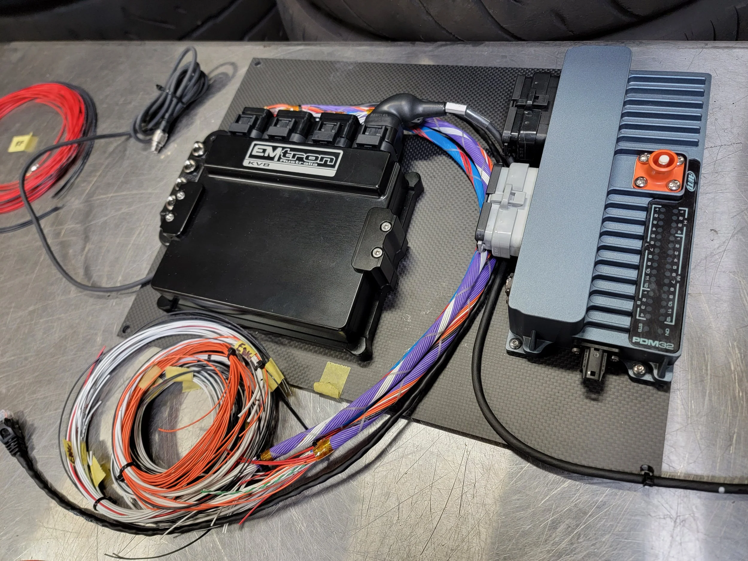
Since I was starting from scratch, I decided to install a PDM (Power Distribution Module). This will simplify the wiring by eliminating the need for fuses and relays and also lets me configure how and when power outputs are enabled. I chose to go with the AiM PDM32, which doubles as a datalogger.
Wiring up the PDM is simple, but time consuming. Anything that needs a power source will be wired to a power output. Sensors and switches can be wired to the inputs. Any engine data from the ECU can be communicated to the PDM via CAN. Here’s an example of how something like the fuel pump circuit can be set up.
The current and status of the channel can be data logged at a few different sampling frequencies.
The output can have a soft start/stop. This would be useful for something like a radiator fan to reduce the inrush current.
You can set the maximum allowed current before the output shuts down. This is your circuit breaker.
You can set how many times you want the output to, “retry”, before considering it being a serious issue. This might help you get through and finish a race for an intermittent short circuit.
You can set a delay for when the circuit turns on and off
My fuel pump is set to turn on when the ECU relay output triggers on and only when the ignition is ON at the same time.
I can also override the fuel pump using the CAN keypad. In this case, I have set one of the buttons to equal “IGN” with a short press. This turns on the ignition power button. With a long press, the button equals, “FP”. This will activate the fuel pump. This can be useful to draining the fuel tank or diagnostic work.
To go with the PDM, I also upgraded to an Emtron KV8 ECU (Thank you Jei at Blacktrax). The KV8 is much more powerful in terms of features and user control compared to what was in the car before.
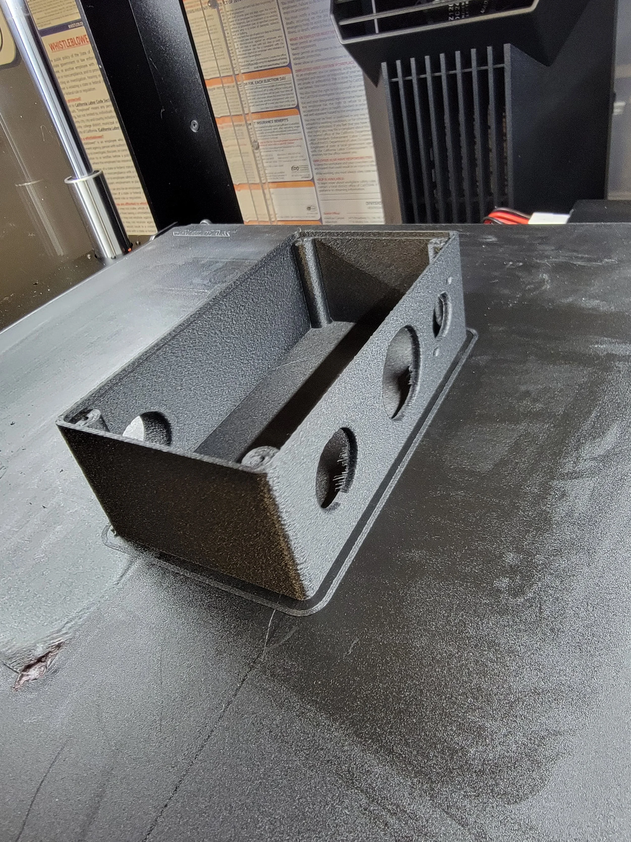
The AiM PDM32 comes with two display options- 6” and a 10”. I ordered the 6”, which is the same size as the MXP that came out of the car. Although the display is the same size as the MXP, the back side is slightly different, so I had to 3D print a new mount for it


Harness Construction
Before I could dive into building the harness, there were a few steps I needed to take to make sure the process went smoothly.
Documentation and planning
This is the most time consuming, but important step of the entire process. I like to use spreadsheets to plan out and document the wiring and this typically includes:
A list of all of the electrical components that will need to be wired. This would include things like a PDM, ECU, CoolShirt, helmet fan, radiator fan, Accusump, brake switch, brake lights, radio, windshield wiper, etc.
A pinout of all of the components with a description of the pin assignment, it’s destination, and the wire I plan to use.
A materials list which includes the connectors, terminals, wire, shrink tubing, shrink boots, etc. needed to build the harness.
Mockup harness
I mounted all of the electrical components in the car and used some rope to build a mockup harness. This helped visualize how I wanted the wires routed and determine the lengths of wire needed for each component.
Harness building plan
For this harness, I went with the concentric twist method. This technique is used to create very flexible harnesses and provides strain relief no matter how the harness is bent. Each individual wire is wrapped in layers which also results in a smaller diameter overall. There are many things to think about and “guidelines” to follow when building this type of harness.
Thicker wires or cables should be the, “core” of the harness.
You generally want to keep the same gauge wire in the same layer
Wires that will branch out before others should be on the outer layers.
No wires should cross over each other and there is a specific lay length spec (length of one rotation per wire)
I’m not going to get too far into how to build one of these harnesses, but as you can see, there is going to be a lot of planning involved. The plan is going to tell me what wire to use, how long it should be, and where it will go. It will also tell me the number of wires, and the direction of rotation by layer. There is a formula to help determine how many wires will fit into each layer depending on the wire size and previous layer diameter. Since a harness is usually made up of shielded cable, twisted pairs, and different gauge wire, there may be some, “filler wire” needed to complete a layer before moving onto the next. With proper planning, you can minimize the amount of, “filler wire” needed. All of this will go into our spreadsheet as well.


As part of the harness, I wanted to add a breakout box, which will have an auxiliary input connector, a USB outlet to charge something like a GoPro, and the ECU comm. connector. I also needed to make a mount for the CAN keypad.


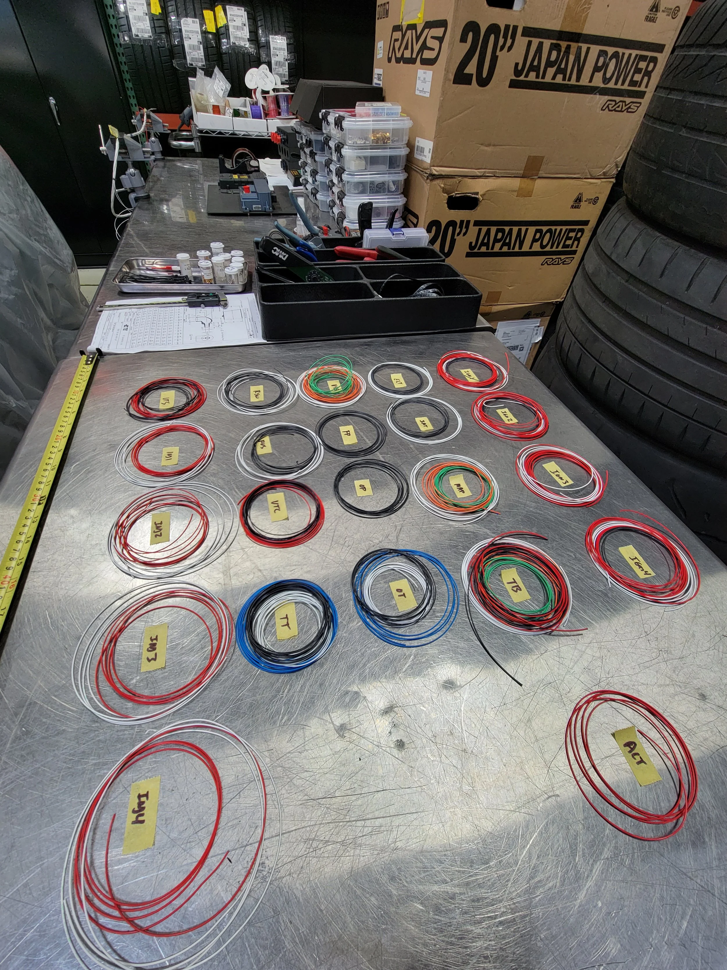
I like to start a harness off by cutting all the wires that I need to length and laying them out. I will then strip the ends, crimp on the pins and put them into the connector that I’m working with. Once the connector is fully pinned, I’ll pull up my spreadsheet and start twisting.


This is the completed harness, which is lighter and nicer looking than what came out of the car. Every connector is labelled to prevent confusion when things have to come back apart in the future.
The engine harness was redone as well, but I unfortunately. didn’t get any photos. That said, the process was almost exactly the same. To make engine removals easier in the future, the engine harness connects with a single bulkhead connector on the firewall. I also added Radlok quick release connectors to the main battery and ground cables.


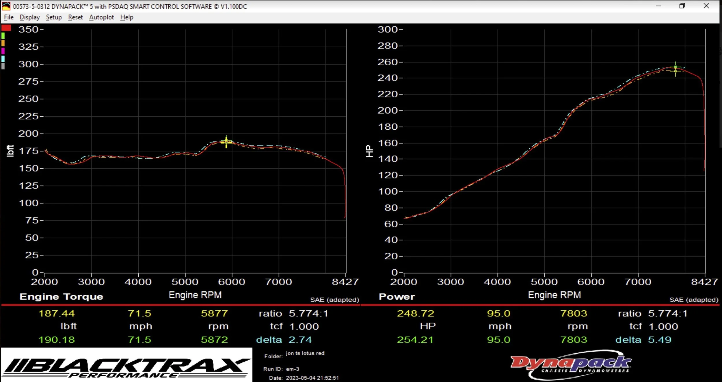
Tuning
With a new ECU, the car had to be tuned again. With no other changes, I was surprised to see that the car had gained 6hp and 10ft lbs of torque! This is likely the result of a more capable ECU, more precise fuel metering, and better DBW control at high RPM.