
Trackspec's Exige S240 Project: Part 10, K24 Swap (2)
When we left off in part one of the K24 swap, we had the engine in the car and started getting things connected. Although it seemed like it was close to being done, there was quite a bit left to do.
Oiling
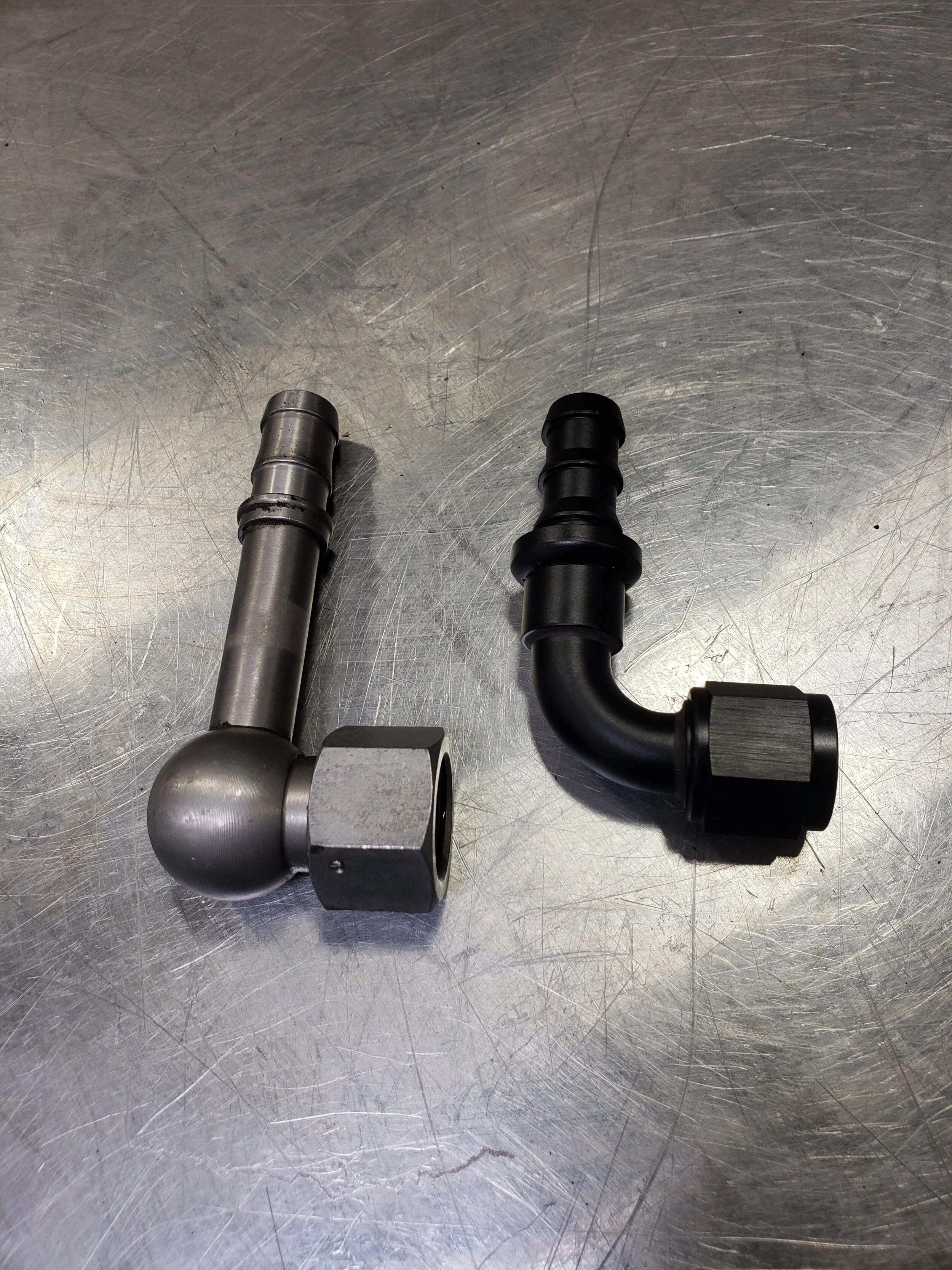
We decided to keep the factory dual oil coolers. This may change in the future, but we wanted to make sure the temps were stable even on extremely hot days. Moving along on the track is one thing, but following closely behind another car in “dirty air” and it can get hot pretty quickly. Because these cars are known to over cool engine oil, we installed a thermostatic sandwich plate with a 200F thermostat to help maintain proper temps. The oil line on the right hand side of the car reached the sandwich plate without any modification, but the left hand side was extended using -10 hose and joined together with a Push Lock union fitting.


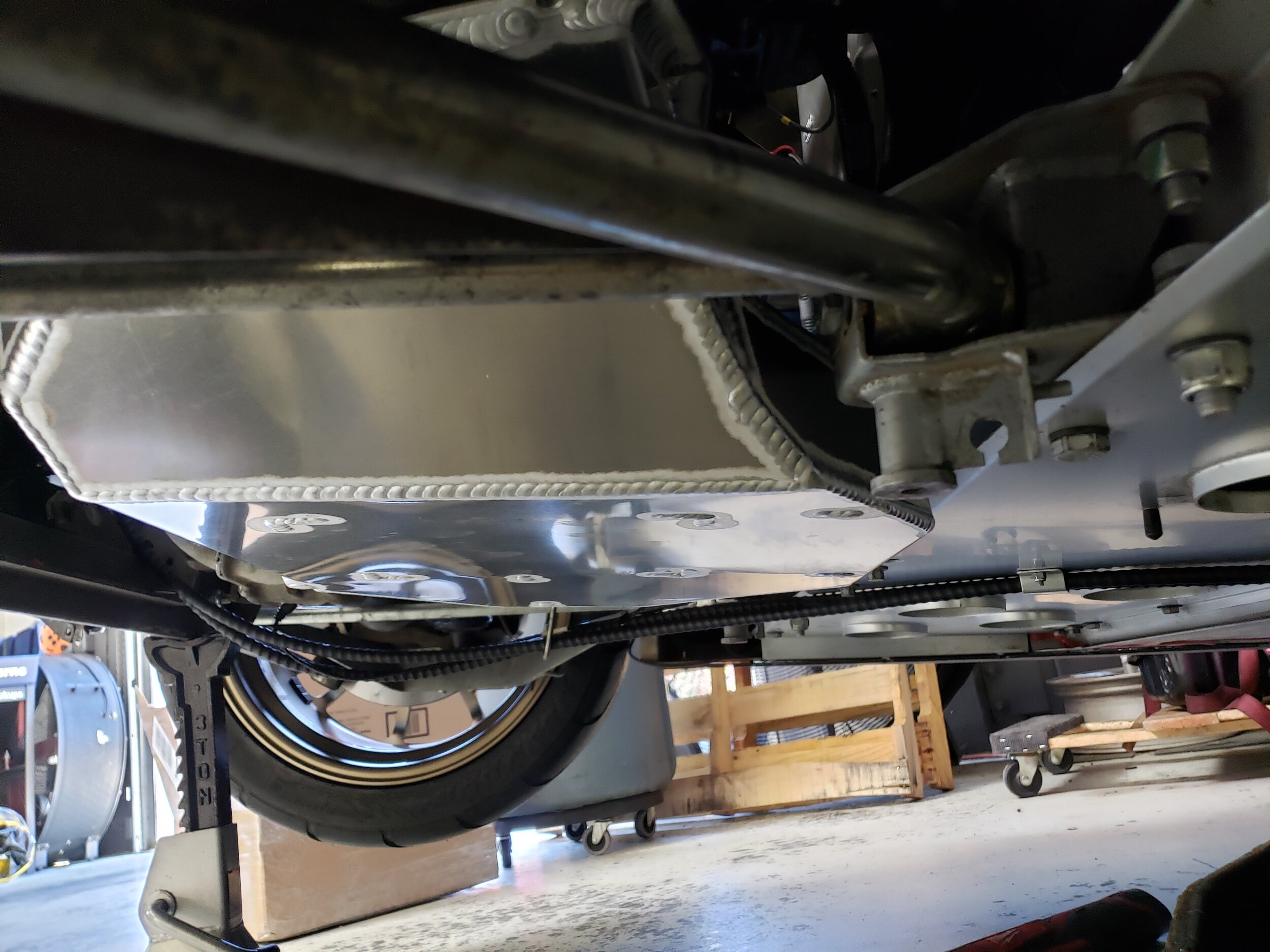
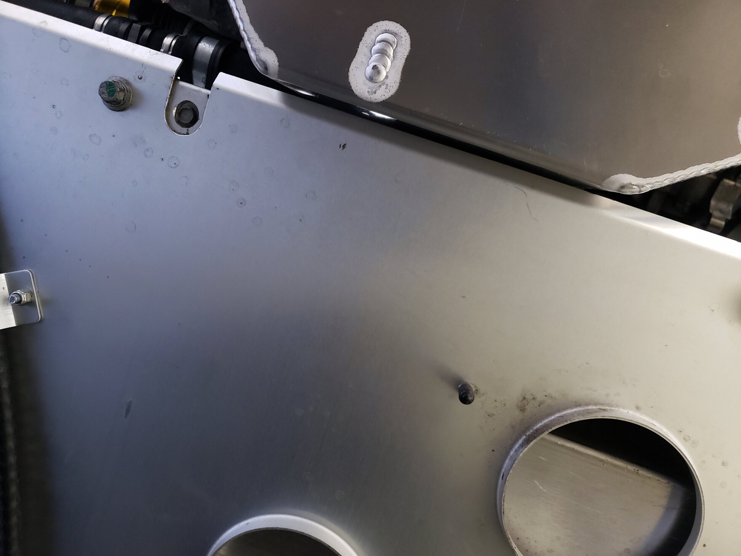
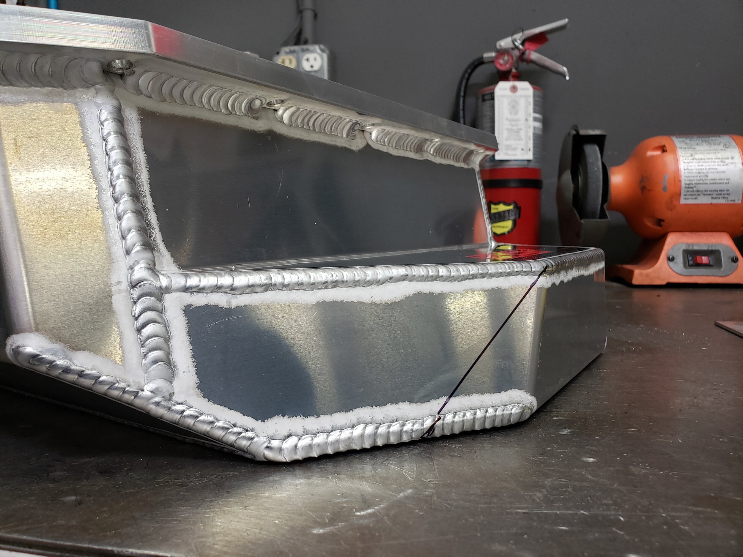
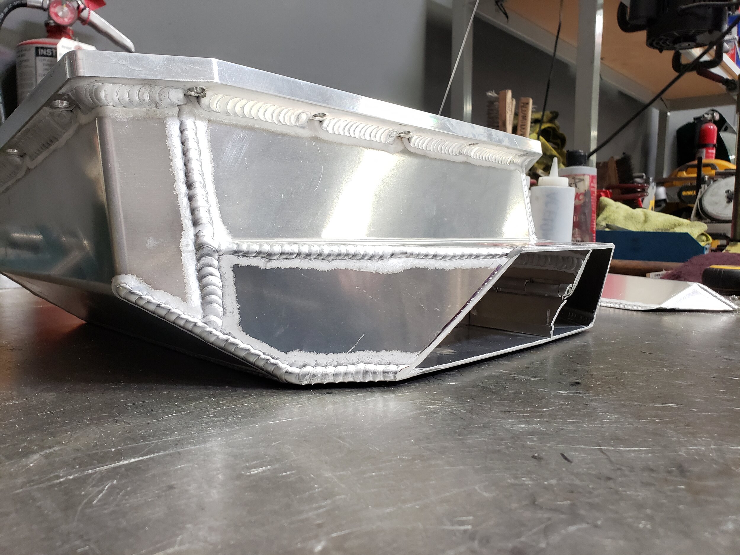
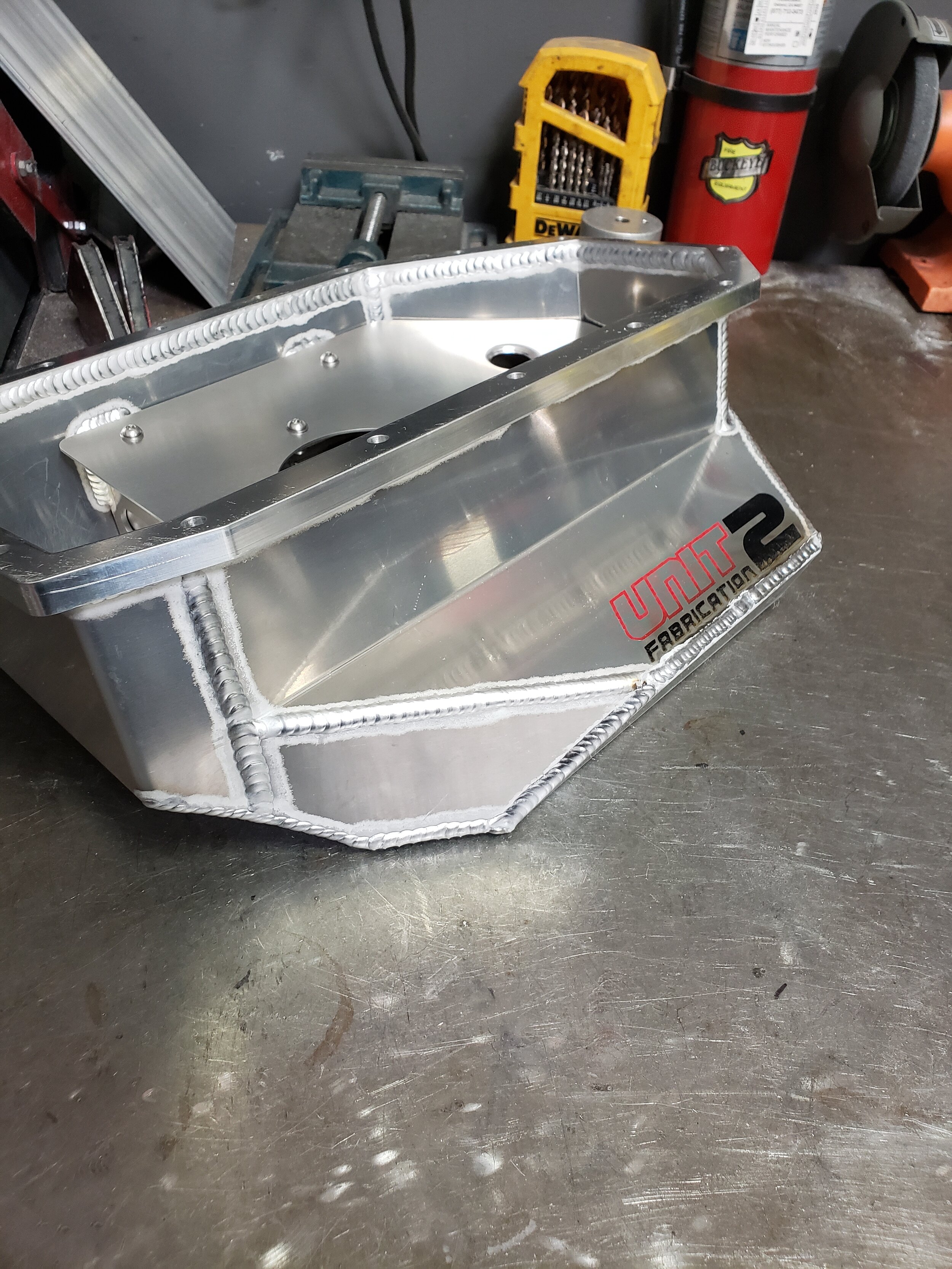
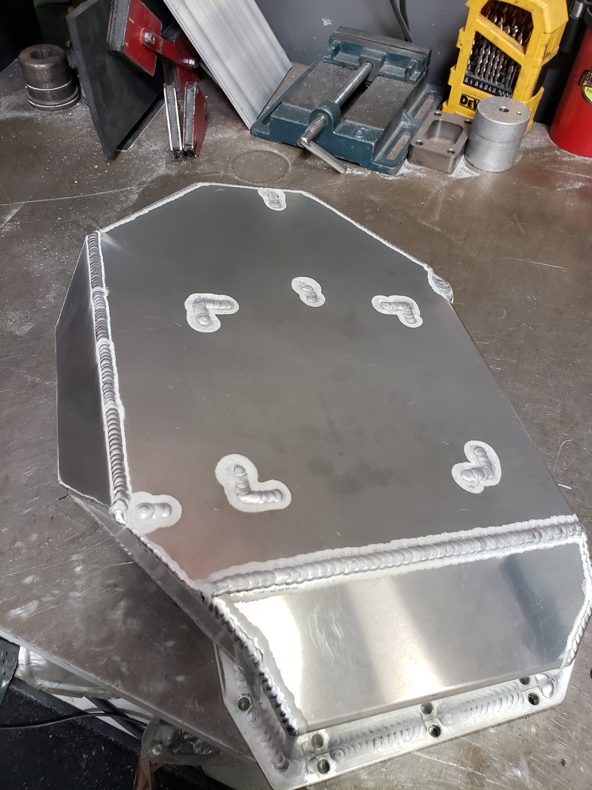
A Unit 2 Fabrication baffled oil pan in conjunction with the Accusump that is already on the car will help maintain oil pressures. What we really like about this specific pan is that there is more than one baffle around the oil pick up. There are also baffled chambers surrounding the main baffle. We were a little concerned about fitment with the large front kick-out since the pan wasn’t designed for our specific application.
The pan fits, but sits very close to the chassis. It will definitely make contact with engine movement, so we had to make a slight modification.
Intake
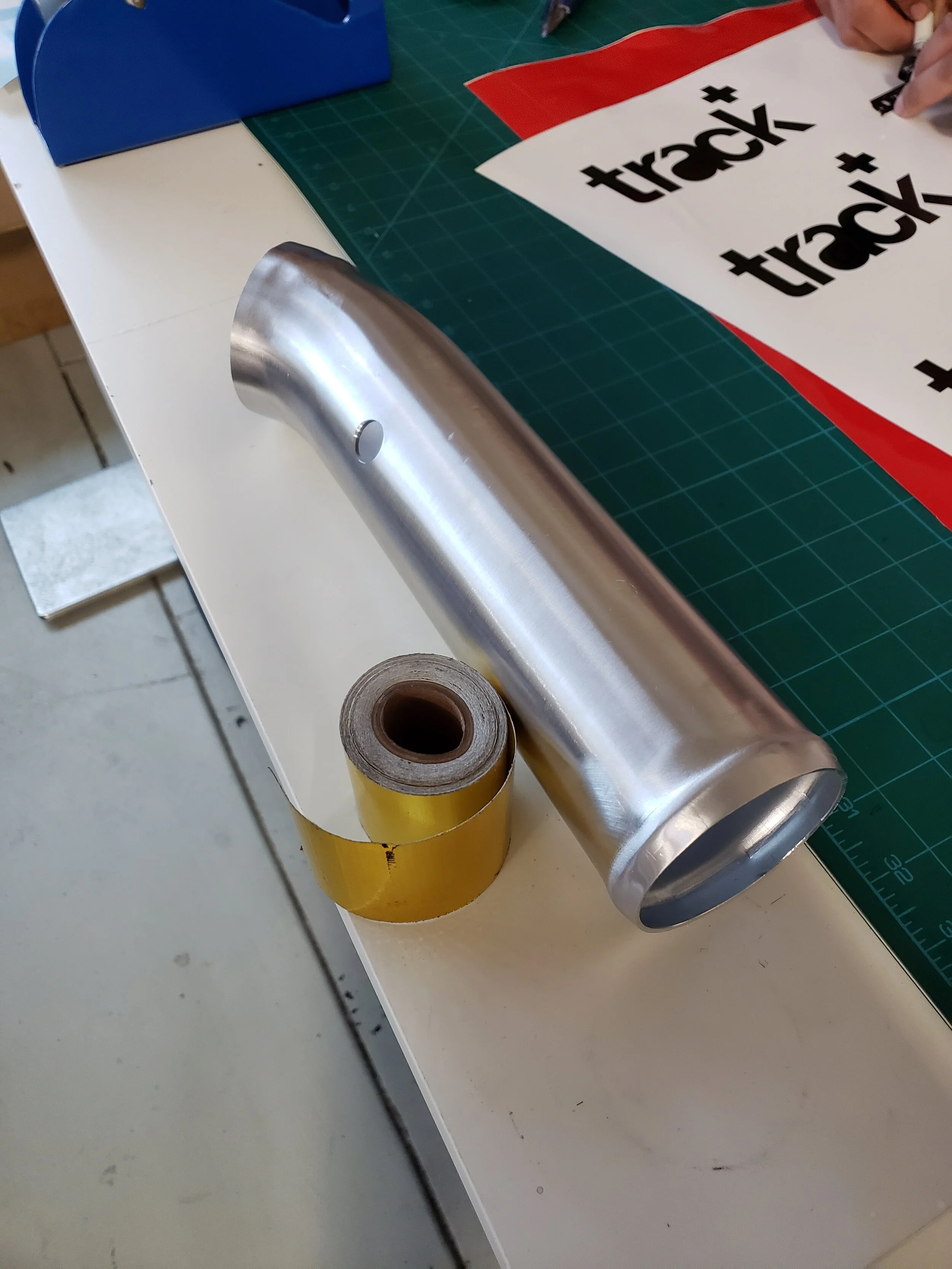
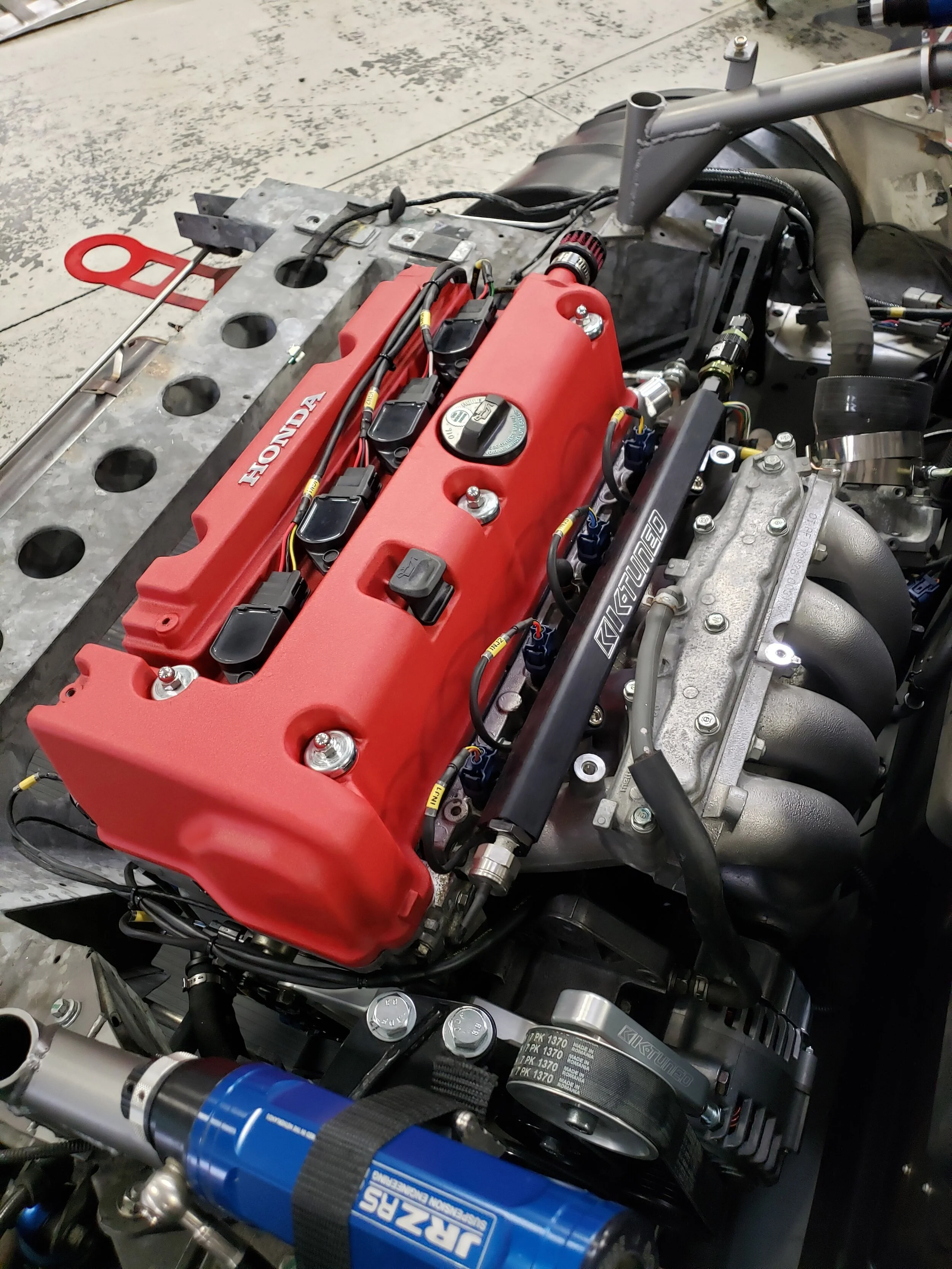
The intake system consists of an ITG aluminum air box with 3” aluminum tubing. We wrapped the intake tube with DEI heat reflective tape to help reduce intake air temps. Does it actually do anything? We haven’t done any testing, but who doesn’t like wrapping things in shiny gold tape?


A single band clamp supports the intake but also allows engine movement.
Engine Management & Wiring
This is the only part of the swap that could make it hard to go back to stock, depending on your approach. Although you can do this swap without cutting up the stock harness, it ends up being much more work and a lot of excess wiring. However, for some people, this is the better option.
That said, even if you cut up the chassis harness, you can still replace it, but it won’t be easy. The advantage of not preserving the stock harness is wiring job that is much more simple and all of the excess wires can be removed from the car.
The most common solution is to run an 02-04 RSX-S engine harness and Hondata Kpro4 ECU. The only problem is that we wanted to keep the drive-by-wire, and Kpro4 doesn’t support that. Keeping the drive-by-wire throttle body will give us throttle tuning control. We could easily make multiple throttle maps to either “de-tune” the engine, or change how we want the throttle plate to open based on throttle input at the pedal.
Both of our J-Swapped S2000 and our S54-Swapped E36 M3 are on AEM Infinity ECUs, so we decided to do the same for the Exige. The ECU supports boost, flex fuel, traction control, launch control, and sequential gearboxes, so there is plenty of room to expand if we ever decide to go a different direction with the car.
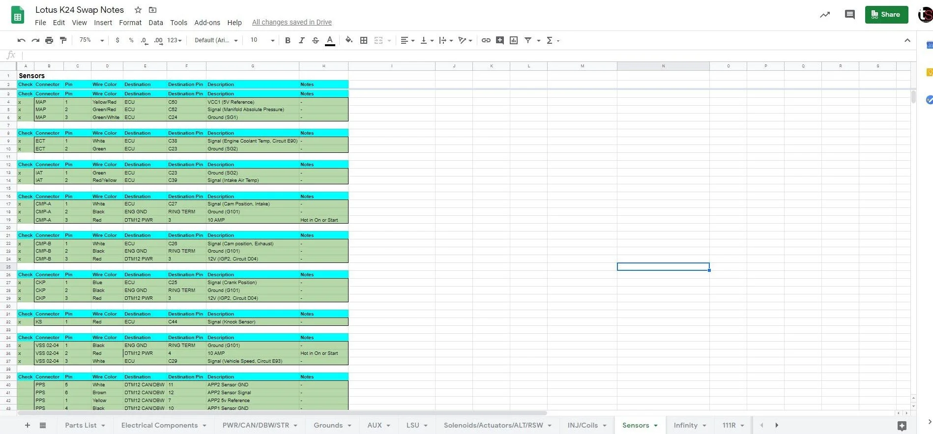
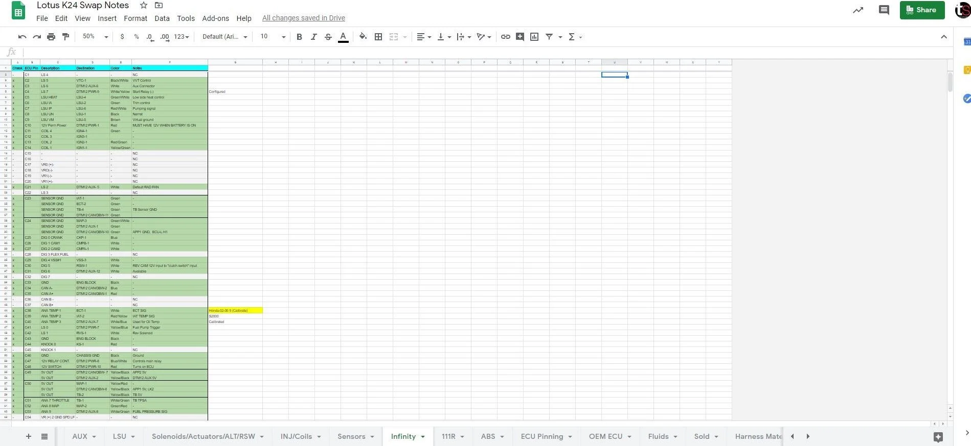
We were originally going to modify a stock RSX engine harness, but decided to tailor one to our specific application and build a custom harness from scratch. In part one, we mocked up the wire harness on the engine with some nylon rope. We used this to draw our harness layout which includes the lengths of each trunk and branch.


TXL wire and a combination of OEM Honda connectors and Deutsch connectors were used to construct the harness. Raychem DR-25, which is a chemical resistant and flame retardant heat shrink tubing was used as the sheathing. Raychem SCL is a semi-rigid dual wall heat shrink which was used to insulate splices, provide strain relief at the branches, and seal off the ends of the DR-25. Future plans for a power distribution module were considered when designing the harness, so when the time comes, we will just need to build a chassis harness that plugs into the engine harness. In other words, all of the required 12v power, inputs and outputs for the engine and ECU will be found in a couple of main connectors inside the cabin.
The most time consuming part of building a wire harness is the planning, but it is worth the time invested. Documenting each wire’s function, destination, color, size, and length is not only going to make the building process easier, but also give the next person working on the car a reference for any diagnostics that may be needed in the future.
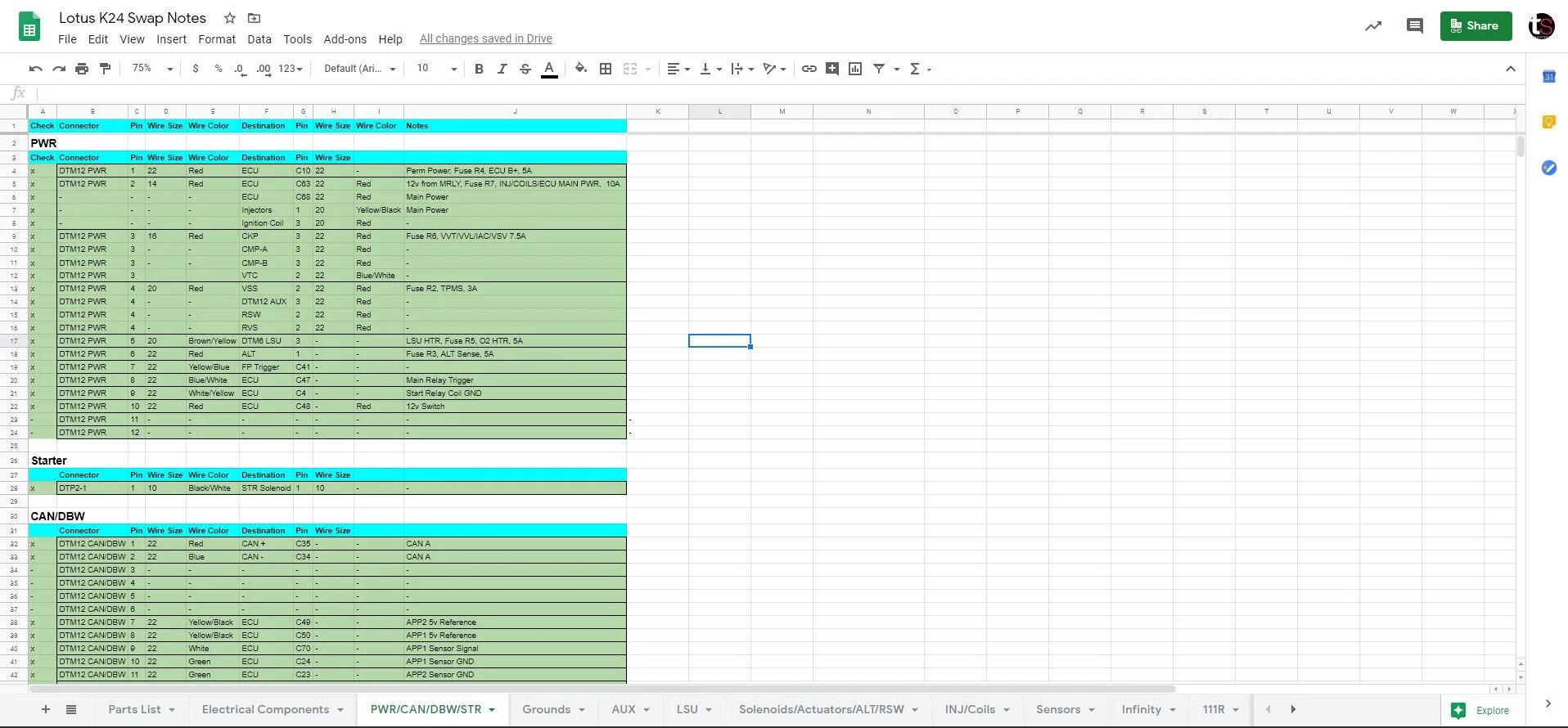
While waiting for the parts to build the harness, we moved over to the chassis side. We started off by going through each wire on the ECU connectors to label the ones we needed to keep and remove the ones that were not going to be used. We will utilize the factory fuses and relays for now. The wires that stayed were:
12v output from fuse R2- To provide power to the vehicle speed sensor, reverse lockout solenoid, and AUX inputs.
12v output from fuse R3- To provide power to the alternator.
12v ouput from fuse R4- To provide permanent power to the ECU.
12v output from fuse R5- To provide power to the wideband oxygen sensor.
12v output from fuse R6- To provide power to the crank sensor, cam sensors, and variable timing control solenoid.
12v output from fuse R7- To provide power to the ignition coils, injectors, and ECU.
12v switched power- To turn on the ECU.
Fuel pump relay trigger- ECU will provide a low side output to turn on the fuel pump.
Main relay trigger. ECU will provide a low side output to switch on the main relay.
Starter relay negative coil- ECU will provide a low side output only when the engine RPM is below 500RPM, so the engine start button will only work when the engine is off. (Start button provides 12v to the starter relay coil when pressed)
12v output from the starter relay- To provide 12v to the starter motor solenoid.
CAN high/low wires- For communication between the ECU and AiM dash.
Six wires from the pedal position sensor- To control the drive-by-wire throttle body.


Harness Construction
The first step in constructing the harness was the wire routing. Ideally, you would want a surface large enough for the entire harness to extend out, but due to the shelter-in-place order, the harness was built in a living room with limited space.
Once the wires are routed, you will need to refer to your documentation and cut the lengths of sheathing you will need. The dual wall heat shrink is used at each of the branch points to help with strain relief.


Before terminating your wires, you will need to put on your labeling materials and more dual wall heat shrink.


The last step was to pin the ECU connector.


Now that the harness is complete, we perform the final continuity checks and make sure each wire ends up in the correct location.
After a long and tedious effort, the harness was complete and ready to fit it into the car. The ECU was mounted inside the cabin along with the relays and fuses. There was some extra wiring that needed to be done on the inside of the car to connect the chassis harness to the engine harness.


Once the engine harness was joined to the chassis harness, we powered up the ECU to make sure everything was working correctly, all of the sensors were calibrated, and all of the base settings were configured.
The build is currently on hold until we receive the header that we ordered. When it gets here, we may need to do some minor fab work to mate it to the existing muffler, and then we can fire it up!
If you’re looking for: